Predicting Assembly’s Structural Performance via System-level Validation Testing
How Autodesk Research is exploring systems engineering
Pictured, Lee Connolly, Nick Markovic, Antony Barker, and Andy Harris
Autodesk Research envisions seamless translation of a product from concept to physical form, with each step in the process interconnected and flowing smoothly from one to the next. This approach can be done by integration of design, manufacturing, and operations using product lifecycle data.
To bring this vision to life, Autodesk Research is exploring the relationship between the digital aspects of design and manufacturing and the physical actions required to realize a product. One component of this research has been the design and manufacturing of a large Unmanned Aerial Vehicle (UAV). The purpose of this UAV is to gather product performance data, providing insights for the next design iteration and optimization. This work highlights predicting UAV assembly’s structural performance via system-level validation testing. Validation is important to ensure the product works as intended and is most effective when it’s balanced with physical testing, therefore it’s essential to weigh the associated risks and costs.
In this blog, we explore the role of validation testing, where the boundaries between the digital and the physical blur, and the concept becomes reality.
Why validate?
It seems like such a simple, singular question but there are distinctions in three key areas that our team needed to make as part of the research process:
- Isn’t simulation good enough to provide the answer?
- It can be expensive in time and budget to do. Can we find another way?
- Are we prepared to carry the risk of not doing it?
Isn’t simulation good enough to provide the answer?
The UAV design work is completed, and we have a 3D CAD model in Fusion. We wanted to simulate a multi-material print build since this was the proposed production method. Simulation of multi-materials is difficult; notoriously, the results can be misleading.
The printer of choice was the Markforged FX20 located in the Autodesk Technology Center, San Francisco. This meant we had the ability to simulate the print in the Eiger software by Markforged. This gave parameters for the packing of carbon fibres into the print to maximize stiffness and weight reduction. The process was completed before printing and at this stage we hit an issue: it wasn’t possible to recreate the simulation from the Eiger software and the hypothesis was that we may have overpacked the print with carbon, making it weaker than anticipated. With design and manufacturing teams at halt, the only way to move forward was by conducting a mechanical stress test, also known as a fatigue test.
It can be expensive in time and budget to do. Can we find another way?
It’s true that an external company or university could conduct a fatigue test; however, this type of service has the potential to be resource-intensive for budgets and timelines. Both are always at a premium, so we set out to conduct fatigue testing in-house, using the equipment available at the Autodesk Technology Centers.
First, let’s dive into what the test needed to do. Testing applies a load, or movement, in a controlled way via robot to the motor mount and repeats it for as many cycles as the team determines necessary. A robot is designed to move from point A to point B and will repeat this movement as many times as we specify. After evaluating the robust suite of robotics available to Autodesk in-house, the Kuka cell located at the Technology Centre, Birmingham was selected.
Are we prepared to carry the risk of not doing it?
This becomes a question of defining what the risk is. What happens if a motor mount is lost during testing? Will it affect the whole UAV assembly, setting back the project timeline and budget? And that’s a best-case scenario: when fatigue testing fails, the results are catastrophic. Fortunately, the industry has come a long way, aided by testing improvements as well as material breakthroughs and their novel applications. Methods can be used that are designed to define risk, Failure Mode Effect Analysis. In this case, the risk was defined as too large to ignore, so fatigue testing was required.
Validation setup
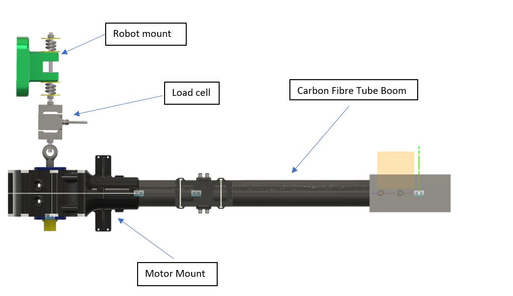
But what does the fatigue test look like? The team needed to determine if it should encompass just the motor mount or the entire assembly, of which it is an integral component. The decision was made to test the whole assembly, including its basic instrumentation. The intent was always to fit strain gauges for inflight data gathering, providing a baseline measurement set that was taken in a stable environment.
“This is an interesting case for system level testing. Component level performance isn’t necessarily correlated with the assembly performance,” said Allin Groom, Senior Research Scientist, Autodesk Research.
Basic Setup
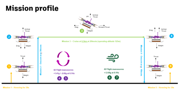
Loading the assembly needed to be consistent with real-world operation, meaning that the application of the load is applied quickly, but not instantaneously. The design team provided a typical mission profile and what the predicted level of deflection would look like.
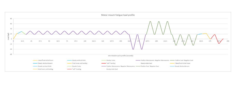
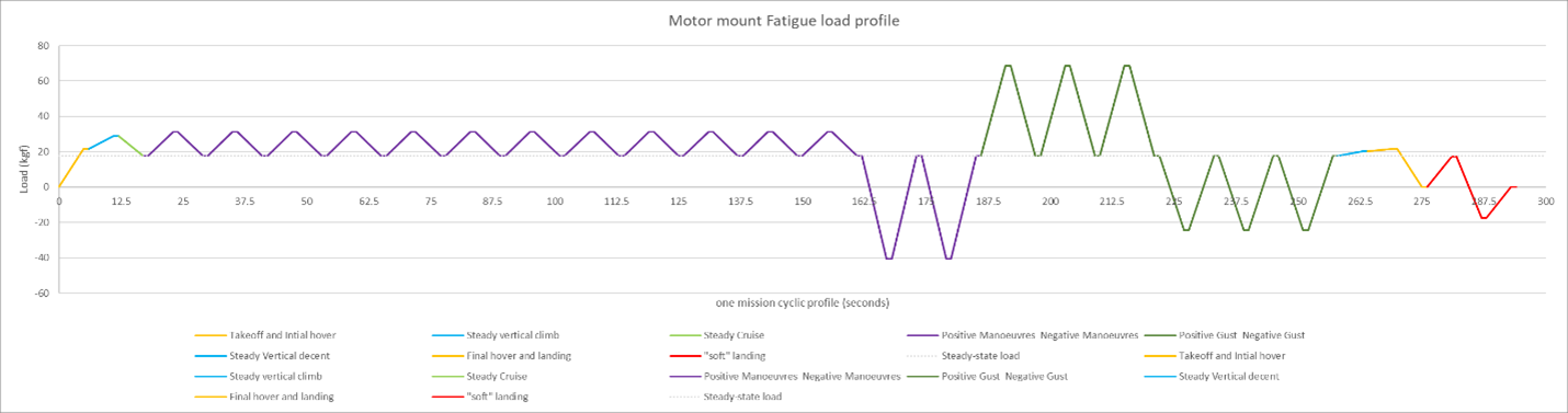
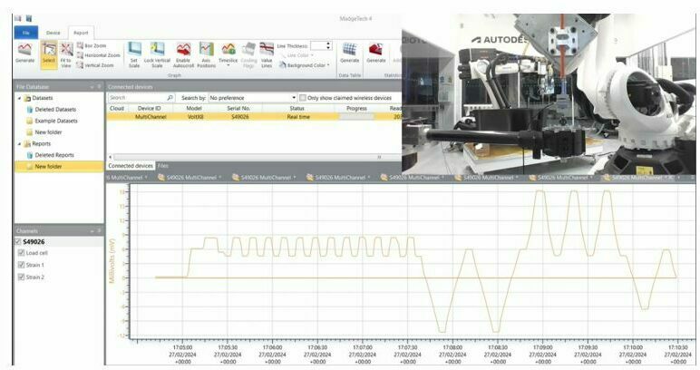
Expected plot of load changes
With the mechanical elements designed and manufactured to allow the attachment to the robots external table and sixth axis (the end of the robot arm), an initial test was undertaken. A spring system that interfaced with the end of arm hardware allowed us to reliably and repeatably convert the linear displacement of the robot into a specified force was also added.
As shown in the plot, the robot followed its programmed mission profile, including the predicted deflection.
The initial success led us to program the robot to repeat cycles, during which we recorded data from the load cell and strain gauges. If any issues were to arise from the applied loads, we expected changes in the data recorded from the load cell. However, throughout the first day, no changes were observed, except for when the robot was stopped due to the cell door being opened.
Results
After two days of testing with no observed decay in the load, we paused the process to inspect the motor mount. Typically, a fatigue test would run until part or assembly failure, but we were curious to check for any internal damage that might not be immediately evident. We did notice a mark in the component that could potentially initiate cracking. However, upon further inspection, we concluded that this mark was a result of an initial printing error, not fatigue-induced delamination. Such printing faults, where layers join, are common and in this instance, did not affect the component’s performance.
The fatigue testing cell was reassembled and has been running for four days with no sign of any problem. This equates to over 700 successful flight missions of the UAV assembly according to the designed flight mission.
The actual test of the assembly passed, ensuring the progression to the production print run of motor mounts, which will ultimately become flying parts. These take over a month to complete 3D printing and are just one of the 1200-parts in the UAV assembly.
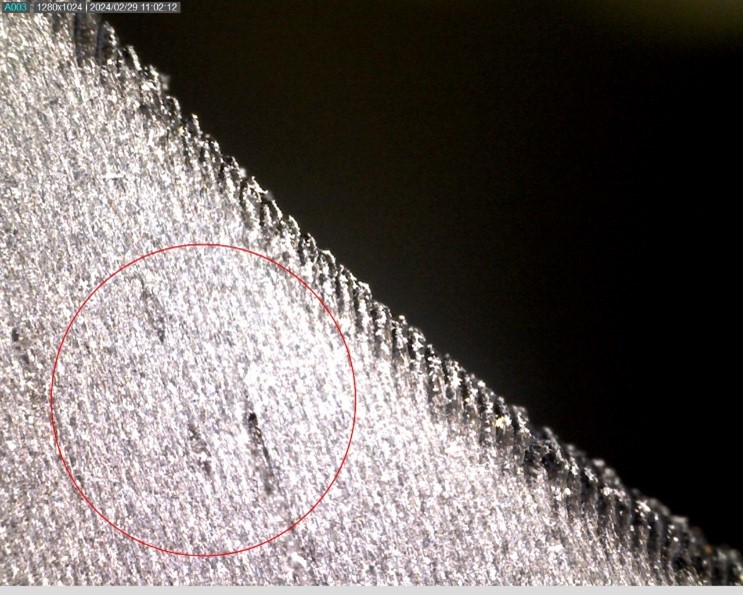
Image from a USB microscope x10 magnification
Overall, we have been able to develop in-house capability to do basic, cost-effective, low frequency fatigue testing on an assembly. This has expanded the knowledge in the team and validated the motor mount before production. The investigation was able to prove out a lighter, cheaper, quicker approach–learnings which can be applied to help both Autodesk and our customers accelerate development timelines.
Conclusions
Autodesk Research’s mission to advance the design and manufacturing industry through the exploration of the interdependencies between digital knowledge and physical actions has taken a step forward. This is evident in the development and validation milestones achieved so far.
The current project has demonstrated the power of our in-house capabilities. It conducted basic low-frequency fatigue testing on an assembly, which significantly enriched our knowledge base. More importantly, it successfully validated the motor mount before it entered production.
This project underscored the critical importance of validation in any workflow, whether it’s for creating an engineering system or writing an innovative code. The need for an independent method of validating a workflow or process should always be integrated into project plans.
While the cost or potential delay might seem discouraging, it’s crucial to weigh these factors against the potential risks of forgoing validation. The key question to ask is: What is the risk if we don’t do it?
Get in touch
Have we piqued your interest? Get in touch if you’d like to learn more about Autodesk Research, our projects, people, and potential collaboration opportunities
Contact us